
How to build UVM Environment Part – 1
In earlier post i.e. https://theartofverification.com/uvm-testbench-architecture/ we learned which all components are required to develop UVM Environment/Testbench to verify complex Designs. In this blog post we will verify a small RTL Design by developing complete UVM Environment.
Let’s start with the basic RTL Design and understand it’s specifications/working.
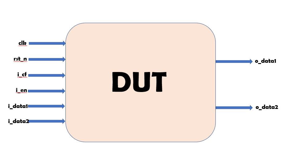
Here as we can see that in the specifications of this RTL as per the diagram we have a block that has two 16 bit data input ports, an enable port, and a 2-bit correction factor port.
If the data on the ports is anything other than 16’h0000 or 16’hFFFF, then the data is multiplied by the correction factor if enable is high. If enable is low, then the output ports maintain their previous value.
Verilog code for above mentioned diagram looks like this
module pipe (clk,
            rst_n,
            i_cf,
            i_en,
            i_data1,
            i_data2,
            o_data1,
            o_data2);

  input         clk;
  input         rst_n;
  input  [1:0]  i_cf;
  input         i_en;
  input  [15:0] i_data1;
  input  [15:0] i_data2;

  output [15:0] o_data1;
  output [15:0] o_data2;

  wire         clk;
  wire         rst_n;
  wire  [1:0]  i_cf;
  wire         i_en;
  wire  [15:0] i_data1;
  wire  [15:0] i_data2;

  reg   [15:0] o_data1;
  reg   [15:0] o_data2;

  reg   [15:0] data_1;
  reg   [15:0] data_2;

  // Store the input data and check to see if it is
  // 16'h0000 or 16'hFFFF
  // If not multiply by correction factor

  always @(posedge clk) begin
    if(!rst_n) begin
      data_1 <= 16'h0000;
      data_2 <= 16'h0000;
    end
    else begin
      if(i_en) begin
       if((i_data1 == 16'h0000) || (i_data1 == 16'hFFFF)) begin
         data_1 <= i_data1;
       end
       else begin
         data_1 <= i_data1 * i_cf;
       end
       if((i_data2 == 16'h0000) || (i_data2 == 16'hFFFF)) begin
         data_2 <= i_data2;
       end
       else begin
         data_2 <= i_data2 * i_cf;
       end
      end
    end
  end

  always @(posedge clk) begin
    o_data1 <= data_1;
    o_data2 <= data_2;
  end
endmodule
Let’s Start to build UVM Testbench
To build a UVM testbench from the ground up, you start with the two most basic elements: the interface and the data transaction. Starting with the transaction, instead of the driver or monitor, allows you to really think about the transactions and sequences that need to be sent. The interface is the element that connects the DUT to the
testbench.
INTERFACE
A SystemVerilog interface is a simple construct that allows communication between the design and the testbench. Driving the interface, as opposed to the actual RTL, aids in reuse as well.
For example, there are two blocks in your design that have the same inputs. Designer A has a coding style where all of his or her inputs and outputs begin with “i_” or “o_” respectively. Designer B does not follow this style.
By using an interface, the signals in that interface can have a generic, yet descriptive name, regardless of the actual RTL port names.
Here’s the interface for the testbench:
interface pipe_if(input logic clk, rst_n);
  logic [1:0]  cf;
  logic [15:0] data_in1;
  logic [15:0] data_in2;
  logic [15:0] data_out1;
  logic [15:0] data_out2;
  logic        enable;
endinterface: pipe_if
DATA PACKET OR SEQUENCE ITEM
class data_packet extends uvm_sequence_item;
  rand bit [1:0]  cf;
  rand bit        enable;
  rand bit [15:0] data_in1;
  rand bit [15:0] data_in2;
  rand bit [15:0] data_out1;
  rand bit [15:0] data_out2;
  rand int        delay;

  constraint timing {delay inside ([0 : 5]);}

  `uvm_object_utils_begin(data_packet)
    `uvm_field_int(cf,        UVM_DEFAULT)
    `uvm_field_int(enable,    UVM_DEFAULT)
    `uvm_field_int(data_in1,  UVM_DEFAULT)
    `uvm_field_int(data_in2,  UVM_DEFAULT)
    `uvm_field_int(data_out1, UVM_DEFAULT)
    `uvm_field_int(data_out2, UVM_DEFAULT)
    `uvm_field_int(delay,     UVM_DEFAULT)
  `uvm_object_utils_end

  function new(string name = "data_packet");
    super.new(name);
  endfunction: new

  virtual task displayAll();
    `uvm_info("DP", $sformatf("cf = %0h enable = %0h data_in1 = %0h data_in2 = %0h data_out1 = %0h data_out2 = %0h delay = %0h", cf, enable, data_in1, data_in2, data_out1, data_out2, delay), UVM_LOW)
  endtask: displayAll

endclass: data_packet
So for each transaction, the driver will drive randomized values of cf, data_in0, data_in1, and enable onto the interface. The monitor will capture the output data on the interface for checking with the scoreboard and coverage analysis. Let’s start building those components now.
Driver
The next step in building the UVM testbench is to construct the driver. The driver requests data transactions from the sequencer. Once it has the transactions, it drives the interface signals in adherence to the protocol.
First, let’s build the driver for the given DUT
class pipe_driver extends uvm_driver #(data_packet);
  virtual interface pipe_if vif;

  `uvm_component_utils(pipe_driver)

  function new(string name, uvm_component parent);
    super.new(name, parent);
  endfunction: new

  function void build_phase(uvm_phase phase);
    super.build_phase(phase);

    if(!uvm_config_db#(virtual pipe_if)::get(this, "", "in_intf", vif))
      `uvm_fatal("NOVIF", {"Virtual Interface must be set for: ", get_full_name(), ".vif"})

      `uvm_info(get_full_name(), "Build Stage Complete", UVM_LOW)
  endfunction: build_phase

  virtual task run_phase(uvm_phase phase);
    fork
      reset();
      get_and_drive();
    join
  endtask: run_phase

  virtual task reset();
    forever begin
      @(negedge vif.rst_n);
      `uvm_info(get_type_name(), "Resetting Signals", UVM_LOW)
      vif.cf = 2'b0;
      vif.data_in1 = 16'b0;
      vif.data_in2 = 16'b0;
      vif.enable = 1'b0;
    end
  endtask: reset

  virtual task get_and_drive();
    forever begin
      while(vif.rst_n != 1'b0) begin
        seq_item_port.get_next_item(req);
        drive_packet(req);
        seq_item_port.item_done();
      end
    end
  endtask: get_and_drive

  virtual task drive_packet(data_packet pkt);
    vif.enable = 1'b0;
    repeat(pkt.delay) @(posedge vif.clk);
    vif.enable = pkt.enable;
    vif.cf = pkt.cf;
    vif.data_in1 = pkt.data_in1;
    vif.data_in2 = pkt.data_in2;
    @(posedge vif.clk);
    vif.enable = 1'b0;
  endtask: drive_packet

endclass: pipe_driver
First, the driver declares the virtual interface, pipe_if, that it will be driving. It then calls the utility macro `uvm_component_utils to enable automation and register this class with the factory. Next is a typical UVM constructor with a string and uvm_component arguments.
The most interesting part of this section is the build_phase where the uvm_config_db is used to obtain the virtual interface. Note, I have encapsulated the call to uvm_config_db in an if statement and inverted it. If the call is unsuccessful, then the `uvm_fatal macro will trigger and end the simulation with a “NOVIF” error.
The next section is the run_phase. Remember, the run_phase is the only phase that consumes time and all test execution occurs during this phase.
This task calls two other tasks, reset and get_and_drive, in a fork/join block for parallel execution. The reset task will reset the signals to 0 based on the status of the active low reset signal. The get_and_drive task will initiate communication with the sequencer to get the transaction.
Notice that in both tasks, the heart of the execution is encased in a forever block. This is necessary so that these threads execute continuously until the end of the simulation. When you are writing your own testbench and accidentally code an infinite forever loop, remember to check that you have a blocking statement in your loop or a statement that advances time. In the reset task, it blocks until the negedge of vif.rst_n.
Let’s examine the get_and_drive task in more detail.
The seq_item_port is used to get items from the sequencer. It calls the task get_next_item which blocks until an item is available. The argument here is “req” which is a data member of the base class uvm_driver, and its type is REQ. REQ stands for request transaction type.
The packet is then sent to the drive_packet task. Once that task has completed, the seq_item_port then calls the item_done task which indicates to the sequencer that the sequence is done.
Finally, the drive_packet task drives the transaction values onto the interface after a randomized delay.


good work Hardik, and The Art of Verification team.
you have narrate UVM. very well and its sound like beginner can pick up easy.
Thank you so much for reading and spreading awareness with beginners to go through blog posts 🙂