

Mastering the SOC Verification Flow: A Comprehensive Guide
Table of Contents
In the intricate world of ASIC Verification, the SOC Verification Flow is a cornerstone process that necessitates both expertise and experience. Many people may not fully understand what sets a system-on-chip (SoC) apart from other semiconductor devices. Within the realm of electronic design automation (EDA), the term “SoC” is often used without a clear definition or explanation of its significance. So, what exactly does SoC mean, and why is verification for SoCs distinct from IP verification? Let’s delve into the world of SoCs and explore the intricacies of their verification process.
A System-on-Chip (SoC) is a complete system integrated into a single chip. It combines functionalities that were previously distributed across multiple chips. For instance, an SoC in a smartphone might include a CPU, GPU, memory, and even wireless modems, all working together to provide a seamless user experience.
Let’s break down the steps of the SOC Verification Flow with real-world examples:
1. Feature Extractions in SOC Verification Flow
The first step involves understanding the design at the top level. For example, if you’re working on an SoC for a smartphone, you might identify features like power management, signal processing, and connectivity. These features are critical for the device’s performance and user experience, and each one needs to be verified individually and in conjunction with others.
2. SoC Level Verification Plan
- Define a Clear Line Between SoC and IP
It’s important to distinguish between functionalities that need to be verified at the SoC level and at the IP level. For instance, while the functionality of a CPU might be verified at the IP level, the interaction between the CPU and memory would be verified at the SoC level. This distinction helps ensure that each component is functioning correctly both independently and as part of the larger system.
- Identify Reusability Components
Look for components that can be reused at the SoC level. For example, if you’ve already developed a verification environment for a CPU at the IP level, you might be able to reuse it at the SoC level. This not only saves time but also ensures consistency across different levels of verification.
- Verify Interconnections
At the SoC level, the focus is on verifying the intercommunication between the sub-blocks. For instance, you might verify that data can be correctly transferred from a CPU to memory and then to a GPU. This ensures that the different components of the SoC can effectively communicate and work together.
- Keep Placeholders for Updates
Sometimes, all features of the SoC are not defined in the initial phase. For such features, update the verification plan at a later stage. For example, if a new wireless standard is released during the verification process, you might need to update your plan to include it. This flexibility allows the verification process to adapt to changes and new developments.
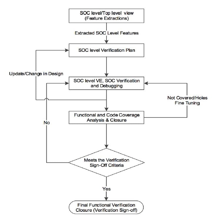
3. SoC Level Verification Environment and SoC Verification
The SoC level verification environment contains sub-block level verification components/environment along with dedicated SoC level verification components/environment.
- SoC Level Verification Methodology
In SOC Verification Flow and the SoC verification, you have to choose the right verification methodology that is best suited for its thorough verification. Along with this, you have to also check in terms of its reusability and its compatibility with the legacy verification environment, if it is available, and if you are going to reuse the same.
For SoC Verification flow, either a mixed methodology/mixed languages-based verification environment or a single standard methodology-based environment is selected based on the SoC’s functionality.
- Integration of Sub IPs/Blocks/Modules/Clusters
Before the actual SoC verification starts, the first step is to integrate/stitch the subblocks/sub-IPs/sub-clusters into the SoC-level verification environment. This is one of the major activities of SoC verification. You also have to develop connectivity checkers which will make sure whether the integration of the sub-blocks to SoC is done properly or not.
This will play a critical role in SoC-level verification because if the integration is not done properly, then you cannot expect SoC-level targeted functionality out of it.
- Legacy Environment/Reusability and New Verification Environment Development
As a part of the reusability and speed of the verification process, first check whether there is a generic legacy verification environment available, which you can reuse for verification.
For example, if you are working on an SoC, check if it is the enhanced version of its previous SoC with some additional functionality and enhancement in it. For this, you can reuse its legacy environment and enhance it to verify the updated functionality in it. You can also reuse sub-block Monitors, Checkers, Assertions, and Reusable/Scalable Test Case
As a part of SoC Verification Flow or Environment development, you need to develop standard verification components like SoC level Drivers, Monitors, Scoreboards/Checkers/Assertions, Reference Models, Functional Coverage, and Top-level Test Bench. For processor-based SoC, generally, a processor is used to configure the whole SoC/its sub-modules and driving the SoC level stimulus. For standard protocols, (like PCIe, Ethernet, USB, etc.) you can also use third-party VIP (Verification IP) available in the market to speed up the verification.
- Verification of the Analog Macros at the SoC level
For analog macros, an equivalent digital reference model from the designer for the SoC-level functional verification is available because, at the SoC level, the analog mix-signal simulation takes more time. Generally, an IP-level team, which owns the respective analog macros will ensure its functionality with analog mix-signal simulation during its verification at the IP level.
- SoC Level Scenarios
At SoC-level verification or SOC Verification Flow, you may require developing SoC-level scenarios to verify its functionality at the top level from an end user’s point of view. If the IP level team has developed reusable/scalable SoC-level test case scenarios then you can reuse the same at the SoC level which will help you speed up the SoC verification. You can also reuse the legacy test case scenarios with some modifications for the similar functionalities of the SoC which were present in its previous version.
- SoC level Debugging
Debugging is a time-consuming process, especially when it comes to the complex SoC verification. A proper understanding of the detailed architecture or the blocks that you need to verify at the SoC level will help you reduce unnecessary debugging time to a great extent.
Use proper coding style and smart message printing with user control verbosity, switch ON the required sub-IP level messages, enable debug switches of the verification methodology, and use proper debugging features of the EDA tool which will help you to quickly debug the RTL as well as the test bench/VE (Verification Environment) issues at SoC level. For example, if you are using UVM, then you can trace the objection activities using +UVM_OBJECTION_TRACE plus an argument on the command line.
During bug filing or any RTL issue reporting, you should provide all the minor details, including the steps to reproduce this issue and the waveform, if applicable to the designer will help him to fix the issue quickly!!!
4. Functional and Code Coverage Closure
Functional and code coverage closure is one of the major milestones for the successful tape out of SoC in SOC Verification Flow. Proper analysis and review of the functional/code coverage will help you close it to 100%. Generally, at the SoC level, cumulative regression results/merging of the consecutive regression results are used to close the functional and code coverage. In the code coverage for the uncovered code, you should have proper justification as to either it is redundant RTL code or that code will be never exercised at the SoC level or it is not covered during functional verification. If the code is not going to be covered at the SoC level or not used for this SoC, then those types of codes have to be added to the exclusion list after the designer’s confirmation.
5. Final Verification Closure (Verification Sign-off)
For the final functional verification closure, you have to fulfill all the functional verification criteria that have been defined in the functional verification sign-off list. For example, 100% functional and code coverage, a consecutive defined number of clean regressions, all bugs closed/fixed, etc. Functional and code coverage will provide confidence in the maturity of the design and its functional verification closure.
I was reading one of the nice articles written by experienced Verification Engineer Dilip Prajapati from eInfochips so this blog refers to his amazing article. I will come back with another interesting blog related to Verification soon till then see ya stay safe and keep on learning to keep on growing 🙂


Hi,
Do you want to write a small article on the following SoC blocks
Clocking and clock control
Resets and reset control
SoC level bump connectivity
Subsystem connectivity
JTAG/Debug access
Register access
Embedded memory access
Interrupts
Power management
Boot sequence
Datapath
Subsystem specific features
SoC level throughput, latency checks
Debug feature connectivity
Functional DFT and BSR connectivity
X-prop and Netlist simulations
Thanks in advance
Hi Subhash,
Definitely, I would love to share maximum knowledge on the above topics but I need your support and help with all the above topics.
Thank you